The quick answer
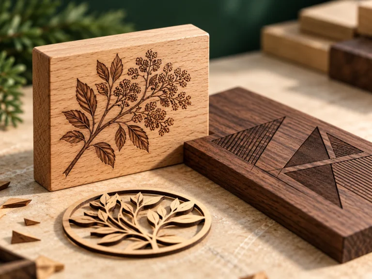
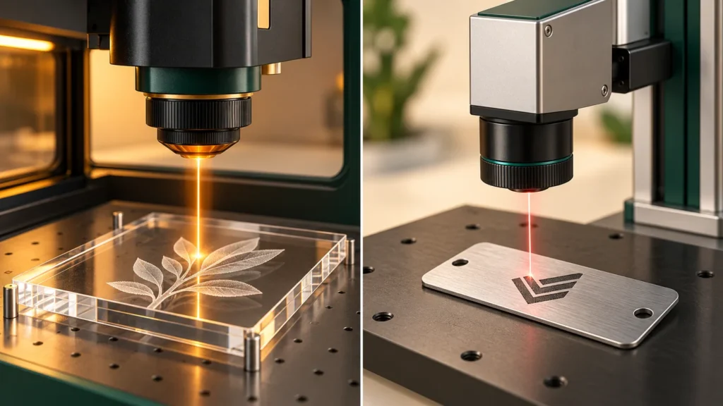
Start with the workpiece and the result. Acrylic displays and wood engraving point toward a different evaluation path from permanent marks on metal components. A laser’s name or wattage alone does not establish that it can perform your job. Manufacturer compatibility guidance separates CO2 engraving/cutting applications from fiber engraving applications; coatings can change the marking method. Epilog compatibility reference.
For this teaching catalogue, LC-900 and LC-1300 illustrate CO2 work-area choices. FM-30 illustrates an enclosed fiber-marking configuration. Their listed values are concept data. None is a verified production machine or a promise that your material will process successfully.
First define what “laser processing” means in your project
Write the desired result as an observable requirement. “A readable batch code on an anodized tag” is more useful than “a powerful laser.” “An acrylic display profile with an agreed edge appearance” is more useful than “a clean cut.”
Cutting separates a profile from a workpiece. Engraving creates a recessed or visibly altered surface. Marking describes an identification result and may involve a surface change rather than a deep recess. Your supplier should explain the proposed method on the actual material and show what the sample demonstrates.
An enclosure, a work-area dimension or a power label does not turn a marking system into a sheet-metal cutter. If your project involves cutting metal stock, request an evaluation for that specific cutting application rather than inferring it from a desktop marker.
Compare the material and the surface together
Use this table to prepare a conversation, not as a machine qualification or a safety clearance.
| Workpiece / task | Evaluation starting point | Information to bring |
|---|---|---|
| PMMA acrylic display or engraved panel | CO2 application review | Grade, cast/extruded identification, thickness, protective film and desired edge/engraving appearance |
| Wood or plywood sign | CO2 application review | Species or board specification, adhesives/coating information, thickness and acceptable surface appearance |
| Two-layer engraving sheet | The sheet supplier’s documented laser process | Exact product code, construction, cap/core, finish and intended service environment |
| Coated or anodized metal label | Review the coating and the requested marking method | Alloy, surface treatment, coating documentation, code size and required durability |
| Bare metal component | Fiber-marking application review or another documented method | Alloy, finish, marking location, geometry and inspection requirement |
These categories describe questions to investigate. They do not assign a universal recipe. Published compatibility guidance also distinguishes bare-metal marking with a marking compound from other CO2 surface applications. Epilog compatibility reference.
Confirm material identity before asking for settings
Two similar-looking plastic sheets can have different compositions. Obtain the exact material specification and safety documentation, including coating, adhesive and protective layers. Have the machine supplier assess the proposed process with that information.
Trotec identifies PVC and PTFE among materials unsuitable for its laser processing because of hazardous by-products. Do not use an unidentified plastic, imitation leather or flame-retardant sheet as an informal trial to discover its composition. A compatibility label for another machine or another material grade is not approval for yours. Trotec material restrictions.
This guide deliberately contains no universal power/speed values. Use the exact equipment manufacturer’s instructions and material-specific process evaluation; an internet setting table cannot establish your installation’s suitability.
Size the working envelope around the real part
Measure the largest workpiece you expect to load, including any fixture, rotary attachment or handling clearance. Record the intended marking area separately from the overall part size. Include an annotated photo when a marking face is recessed, curved or difficult to reach.
Then compare the proposed configuration using the same questions: can the part be loaded, supported, positioned and processed as intended? Ask how the chosen optics, bed or fixture affect that answer. Do not compare two model names while leaving the workpiece description incomplete.
In the Lumacore examples, a 900 × 600 mm concept bed and a 1300 × 900 mm concept bed illustrate a size comparison only. They do not establish usable clearance, achievable output or suitability for a production task.
Use one sample brief for every supplier
A consistent brief makes responses easier to compare. Include:
- Exact material and supplier product code, with relevant documentation.
- An annotated drawing or photograph showing the part and processing area.
- The artwork, text or code to be reproduced, at the intended size.
- The result you will inspect: contrast, dimensions, edge appearance or another agreed criterion.
- A representative sample, including the normal coating and protective layers.
- Expected mix of parts and your handling or integration constraints.
- The evidence you need before making a purchase decision.
Ask the evaluator to identify the equipment configuration and material used for the returned sample. Where a process time is quoted, ask what operations it includes. A short video or a photograph should not silently replace an agreed acceptance measurement.
Questions worth asking before requesting a quotation
Can the same system cover both my wood jobs and metal tags?
Describe both jobs separately. Some manufacturers offer combined-source systems, while other workflows use separate equipment. Request evidence for each material/result combination rather than assuming one successful sample covers the other.
Should I buy the highest available power?
Ask which configuration meets the intended result and why. Power is one input alongside the process, optics, workpiece, handling and installation. Compare complete proposed workflows rather than ranking an isolated number.
What should be included in the equipment proposal?
Request a clearly bounded configuration, stated exclusions, installation requirements, training/support scope and the sample acceptance basis. Commercial terms and compliance documentation should describe the actual offered equipment, not this fictional catalogue.
Turn your material into a useful next step
Prepare the sample brief, then review the relevant material guide and concept system. The next action is a conversation about a defined workpiece and result—not a claim that one source is universally better.